Blinn-Phong Reflectance Model

分为三部分:

  • Specular highlights
  • Diffuse reflection
  • Ambient lighting

L=La+Ld+Ls\it{L = L_a + L_d + L_s}

定义如下量(都是单位向量):

  • l\mathbf{l}: shading point 指向光源的方向
  • n\mathbf{n}: 法线方向
  • v\mathbf{v}: shading point 指向观测点方向

Diffuse Reflection

  • 考虑一个 shading point 接收到了多少能量,与法线和光照方向的夹角大小(nl\mathbf{n · l})有关
  • 光线能量有衰减:I=Ir2I' = {I \over r^2}
  • 不同表面吸收不同颜色的光线能力不同:kdk_d (color)

Ld=kd(I/r2)max(0,nl)\it{L_d} = \it{k_d(I/r^2)}max(0, \mathbf{n · l})

Specular Term

  • 出射方向与 v\mathbf{v} 接近时更容易观测到高光     \iff 半程向量方向接近于法线方向(半程向量即 l\mathbf{l}v\mathbf{v} 的角平分线方向)
  • 使用半程向量是因为它好算
  • 指数 pp 是因为 cosαcos\alpha 容忍度太高,会显得高光区域很大,正常情况下用 (100,200) 范围内的值

Ls=ks(I/r2)max(0,cosα)p=ks(I/r2)max(0,nh)p\it{L_s} = \it{k_s(I/r^2)}max(0, cos\alpha)^p = \it{k_s(I/r^2)}max(0, \mathbf{n · h})^p

where h=bisector(v,l)=v+lv+l\text{where } \mathbf{h} = bisector(\mathbf{v, l}) = {\mathbf{v+l} \over ||\mathbf{v+l}||}

Ambient Term

是一个常数,假设物体所有地方有一个常数的颜色,用来保证没有一个地方完全是黑的。

La=KaIa\it{L_a = K_a I_a}

Blinn-Phong Reflection Model

L=La+Ld+Ls=kaIa+kd(I/r2)max(0,nl)+ks(I/r2)max(0,nh)p\begin{aligned} \it{L = L_a + L_d + L_s} = \it{k_a I_a + k_d(I/r^2)}max(0, \mathbf{n·l}) + \it{k_s(I/r^2)}max(0, \mathbf{n·h})^p \end{aligned}

Shading Frequencies

  • flat shading: 每个三角形内部的点用一样的法线
  • gouraud shading: 每个顶点有其法线,三角形内部颜色通过插值求出
  • Phong shading: 每个像素利用顶点法线插值出其法线

顶点的法线求法是相邻所有面的法线做平均(如果考虑三角形面积,效果会更好):

Nv=iNiiNi\it{N_v}={\sum_i \it{N_i} \over ||\sum_i \it{N_i}||}

使用重心坐标插值出三角形内不同点的法线。

(Real-time Rendering) Pipeline

Shader Programs

  • 顶点着色器、片段着色器
  • 只要写一个顶点或者片段的处理方式就好了
  • 对于 OpenGL,使用 GLSL 来描述
  • 老师推荐的 Shader 网站 shadertoy
  • 现在还有其他着色器可以被定义

Texture Mapping

  • 物体表面有不同颜色,反映到公式里面可以是 Ld\it{L_d} 中的 kd\it{k_d} 在不同点有不同取值
  • 物体表面可以展开成平面,放一张图在上面,叫做“纹理” (texture)
  • 纹理坐标 (u,v)(u,v)uuvv 都在 [0,1][0,1] 范围内,三角形每一个顶点都对应一个纹理坐标
  • tileable map 可以左右无缝衔接
  • 使用插值获得三角形内部像素的纹理坐标

重心坐标 (Barycentric Coordinates)

为了做三角形内部的插值引入的,需要插值的原因:

  • 很多操作是在顶点上完成的
  • 三角形内部需要平滑过渡(纹理坐标、颜色、法线)

重心坐标三角形内任意一个点 (x,y)(x, y) 可以表示成三角形三个顶点的组合:

(x,y)=αA+βB+γC where α+β+γ=1(x, y) = \alpha A + \beta B + \gamma C \text{ where } \alpha + \beta + \gamma = 1

此时坐标 (α,β,γ)(\alpha, \beta, \gamma) 即为点 (x,y)(x, y) 的重心坐标,如果点在三角形内,则 α,β,γ\alpha, \beta, \gamma 均非负。

  • 知道 α,β\alpha, \beta 之后可以这样求 γ\gammaγ=1αβ\gamma = 1 - \alpha - \beta
  • 从几何来看,α\alpha 等于 AA 点对面的三角形面积与整个三角形面积的比值,β,γ\beta, \gamma 以此类推。
  • 三角形重心的重心坐标即为 (13,13,13)({1 \over 3}, {1 \over 3}, {1 \over 3})
  • 对于一般的点:

α=(xxB)(yCyB)+(yyB)(xCxB)(xAxB)(yCyB)+(yAyB)(xCxB)β=(xxC)(yAyC)+(yyC)(xAxC)(xBxC)(yAyC)+(yByC)(xAxC)\begin{aligned} \alpha = {-(x - x_B)(y_C - y_B) + (y - y_B)(x_C - x_B) \over -(x_A - x_B)(y_C - y_B) + (y_A - y_B)(x_C - x_B)} \\ \beta = {-(x - x_C)(y_A - y_C) + (y - y_C)(x_A - x_C) \over -(x_B - x_C)(y_A - y_C) + (y_B - y_C)(x_A - x_C)} \end{aligned}

知道重心坐标 (α,β,γ)(\alpha, \beta, \gamma) 之后,三角形内各个点属性的插值为:

V=αVA+βVB+γVCV = \alpha V_A + \beta V_B + \gamma V_C

但有一个问题:投影变换之后不满足。所以计算三维空间中的三角形,需要用三维坐标来计算插值。

Applying Texture

对于屏幕上每一个采样点 (x,y)(x, y),我们知道其纹理坐标 (u,v)(u, v),查询纹理贴图,设置为 Ld\it{L_d} 中的 kd\it{k_d}

Texture Magnification

纹理小了

会出现颗粒,做模糊:

  • Nearest
  • Bilinear
  • Bicubic

Bilinear Interpolation:

  • 找到临近的四个像素
  • 计算其与四个像素的水平与垂直距离
  • 使用线性插值函数 lerp(x,v0,v1)=v0+x(v1v0)lerp(x, v_0, v_1) = v_0 + x(v_1 - v_0) 做两次水平插值,用得到的结果做一次垂直插值,得到插值结果

Bicubic Interpolation:

  • 使用周围16个像素做插值

纹理大了

会出现摩尔纹,反走样(范围查询):

  • 超采样: 计算量太大
  • mipmap: 一个像素点内信号变化过快,我们就用 mipmap 来降低信号变化频率。近似的范围查询,但只能做正方形的范围查询。

mipmap(图来自维基百科):

Wikipedia

  • 将纹理分辨率缩小一半,生成一个新纹理,反复缩小直到不能缩小。多了 13{1 \over 3} 的存储空间
  • 求像素与其相邻的两个像素(比如上、右)的纹理坐标,看两个像素的纹理坐标之间的距离,取两个距离的较大值 L\it{L}
  • 所需要查询的mipmap层数即为 D=log2L\it{D} = log_2\it{L}
  • 但会发现所查的层数不连续,可以用相邻两层查询到的颜色值做插值,叫做三线性插值 (Trilinear Interpolation)

三线性插值 mipmap 会出现 overblur,使用各向异性过滤 (Anisotropic Filtering) 来解决(图来自维基百科):
Wikipedia

  • 可以查询矩形范围,仍然没法解决斜着的矩形区域,总共开销变成了原本的三倍
  • 游戏中只要显存足够,各向异性过滤可以开高,几乎不会对运算有影响

其他过滤方法:

  • EWA 过滤:拆成多次的圆形查询

Applicatons of Textures

  • 环境贴图,会假设环境非常大,光线来自无限远,只存光线的方向
    • Spherical Environment Map
    • Cube Map
  • 凹凸贴图/法线贴图 (Bump / Normal mapping)
    • 通过定义凹凸的相对变化,改变法线,从而影响着色
    • 原本的法线 n=(0,0,1)n = (0, 0, 1)
    • 用相邻两个像素求切线,再将其逆时针旋转90°得到法线:n=(dp/du,dp/dv,1).normalized()n' = (-dp/du, -dp/dv, 1).normalized()
    • 将得到的 nn' 转换回世界坐标中
  • 位移贴图 (Displacement mapping)
    • 作用于顶点,实际改变几何
    • 要求三角形足够细
    • 可以用动态曲面细分来让模型三角形足够细
  • 3D Procedural Noise
    • 定义噪声解析式,用三维空间中的坐标可以求出噪声值
  • 用来记录已经算好的信息
    • 环境光遮蔽纹理
  • 三维纹理
    • 体积渲染

作业3

在这次编程任务中,我们会进一步模拟现代图形技术。我们在代码中添加了 Object Loader(用于加载三维模型), Vertex Shader 与 Fragment Shader,并且支持了纹理映射。

而在本次实验中,你需要完成的任务是:

  1. 修改函数 rasterize_triangle(const Triangle& t) in rasterizer.cpp: 在此处实现与作业 2 类似的插值算法,实现法向量、颜色、纹理颜色的插值。
  2. 修改函数 get_projection_matrix() in main.cpp: 将你自己在之前的实验中实现的投影矩阵填到此处,此时你可以运行 ./Rasterizer output.png normal来观察法向量实现结果。
  3. 修改函数 phong_fragment_shader() in main.cpp: 实现 Blinn-Phong 模型计算 Fragment Color.
  4. 修改函数 texture_fragment_shader() in main.cpp: 在实现 Blinn-Phong的基础上,将纹理颜色视为公式中的 kd,实现 Texture Shading Fragment Shader.
  5. 修改函数 bump_fragment_shader() in main.cpp: 在实现 Blinn-Phong 的基础上,仔细阅读该函数中的注释,实现 Bump mapping.
  6. 修改函数 displacement_fragment_shader() in main.cpp: 在实现 Bump mapping 的基础上,实现 displacement mapping.

题解

  1. 上次作业已经算出来了重心坐标 (α,β,γ)(\alpha, \beta, \gamma),但只用了它来对深度进行插值。这次可以利用重心坐标对其他量做插值:

rasterizer.cpp

1
2
3
4
5
6
7
8
9
10
11
12
13
14
15
16
17
18
19
20
21
22
23
24
25
26
27
28
29
30
31
32
33
34
35
36
37
38
39
40
41
42
43
44
45
46
47
48
49
50
51
52
53
54
55
56
57
//Screen space rasterization
void rst::rasterizer::rasterize_triangle(const Triangle& t, const std::array<Eigen::Vector3f, 3>& view_pos)
{
// TODO: From your HW3, get the triangle rasterization code.
// TODO: Inside your rasterization loop:
// * v[i].w() is the vertex view space depth value z.
// * Z is interpolated view space depth for the current pixel
// * zp is depth between zNear and zFar, used for z-buffer

// float Z = 1.0 / (alpha / v[0].w() + beta / v[1].w() + gamma / v[2].w());
// float zp = alpha * v[0].z() / v[0].w() + beta * v[1].z() / v[1].w() + gamma * v[2].z() / v[2].w();
// zp *= Z;

// TODO: Interpolate the attributes:
// auto interpolated_color
// auto interpolated_normal
// auto interpolated_texcoords
// auto interpolated_shadingcoords

// Use: fragment_shader_payload payload( interpolated_color, interpolated_normal.normalized(), interpolated_texcoords, texture ? &*texture : nullptr);
// Use: payload.view_pos = interpolated_shadingcoords;
// Use: Instead of passing the triangle's color directly to the frame buffer, pass the color to the shaders first to get the final color;
// Use: auto pixel_color = fragment_shader(payload);

auto v = t.toVector4();

// Find out the bounding box of current triangle.
int min_x = std::floor(std::min({ v[0].x(), v[1].x(), v[2].x() }));
int max_x = std::ceil(std::max({ v[0].x(), v[1].x(), v[2].x() }));
int min_y = std::floor(std::min({ v[0].y(), v[1].y(), v[2].y() }));
int max_y = std::ceil(std::max({ v[0].y(), v[1].y(), v[2].y() }));

for (int x = min_x; x <= max_x; x++) {
for (int y = min_y; y <= max_y; y++) {
if (insideTriangle(x+0.5f, y+0.5f, t.v)) {
auto[alpha, beta, gamma] = computeBarycentric2D(x, y, t.v);
float w_reciprocal = 1.0/(alpha / v[0].w() + beta / v[1].w() + gamma / v[2].w());
float z_interpolated = alpha * v[0].z() / v[0].w() + beta * v[1].z() / v[1].w() + gamma * v[2].z() / v[2].w();
z_interpolated *= w_reciprocal;

auto normal_interpolated = alpha*t.normal[0] + beta*t.normal[1] + gamma*t.normal[2];
auto color_interpolated = alpha*t.color[0] + beta*t.color[1] + gamma*t.color[2];
auto textureCoord_interpolated = alpha*t.tex_coords[0] + beta*t.tex_coords[1] + gamma*t.tex_coords[2];
auto shadingCoord_interpolated = alpha*view_pos[0] + beta*view_pos[1] + gamma*view_pos[2];

if (z_interpolated < depth_buf[get_index(x, y)]) {
fragment_shader_payload payload(color_interpolated, normal_interpolated.normalized(), textureCoord_interpolated, texture ? &*texture : nullptr);
payload.view_pos = shadingCoord_interpolated;
auto pixel_color = fragment_shader(payload);
Eigen::Vector2i point(x, y);
set_pixel(point, pixel_color);
depth_buf[get_index(x, y)] = z_interpolated;
}
}
}
}
}
  1. 将上次作业的 projection matrix 实现复制过来:

main.cpp

1
2
3
4
5
6
7
8
9
10
11
12
13
Eigen::Matrix4f get_projection_matrix(float eye_fov, float aspect_ratio, float zNear, float zFar)
{
// TODO: Use the same projection matrix from the previous assignments
Eigen::Matrix4f projection;
eye_fov = eye_fov * MY_PI / 180.0;
float ty = -1.0 / std::tan(eye_fov / 2.0);
projection << (ty / aspect_ratio), 0, 0, 0,
0, ty, 0, 0,
0, 0, (zNear+zFar)/(zNear-zFar), (-2.0*zNear*zFar)/(zNear-zFar),
0, 0, 1, 0;

return projection;
}

此时运行 ./Rasterizer assignment3_normal.png normal,得到如下图片:

  1. 使用如下公式完成 phong_fragment_shader:

L=La+Ld+Ls=kaIa+kd(I/r2)max(0,nl)+ks(I/r2)max(0,nh)p\begin{aligned} \it{L = L_a + L_d + L_s} = \it{k_a I_a + k_d(I/r^2)}max(0, \mathbf{n·l}) + \it{k_s(I/r^2)}max(0, \mathbf{n·h})^p \end{aligned}

main.cpp - function phong_fragment_shader

1
2
3
4
5
6
7
8
9
10
11
12
13
14
15
16
Eigen::Vector3f v = ( -point).normalized(); // camera at (0, 0, 0)
for (auto& light : lights)
{
// TODO: For each light source in the code, calculate what the *ambient*, *diffuse*, and *specular*
// components are. Then, accumulate that result on the *result_color* object.

Eigen::Vector3f l = (light.position - point).normalized();
Eigen::Vector3f h = ((l + v) / 2.0f).normalized();
float r2 = (light.position - point).squaredNorm();

auto L_a = ka.cwiseProduct(amb_light_intensity);
auto L_d = kd.cwiseProduct(light.intensity / r2 * MAX(0.0f, normal.dot(l)));
auto L_s = ks.cwiseProduct(light.intensity / r2 * std::pow(MAX(0.0f, normal.dot(h)), p));

result_color += L_a + L_d + L_s;
}

此时运行 ./Rasterizer assignment3_phong.png phong,得到如下图片:

  1. 使用插值出来的纹理坐标查询纹理颜色,光照模型使用步骤 3 同款:

main.cpp - function texture_fragment_shader

1
2
3
4
5
6
7
8
9
10
11
12
13
14
15
16
17
18
19
20
21
22
23
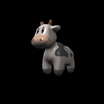
if (payload.texture)
{
// TODO: Get the texture value at the texture coordinates of the current fragment
return_color = payload.texture->getColor(payload.tex_coords.x(), payload.tex_coords.y());
}

// ...

Eigen::Vector3f v = ( -point).normalized(); // camera at (0, 0, 0)
for (auto& light : lights)
{
// TODO: For each light source in the code, calculate what the *ambient*, *diffuse*, and *specular*
// components are. Then, accumulate that result on the *result_color* object.
Eigen::Vector3f l = (light.position - point).normalized();
Eigen::Vector3f h = ((l + v) / 2.0f).normalized();
float r2 = (light.position - point).squaredNorm();

auto L_a = ka.cwiseProduct(amb_light_intensity);
auto L_d = kd.cwiseProduct(light.intensity / r2 * MAX(0.0f, normal.dot(l)));
auto L_s = ks.cwiseProduct(light.intensity / r2 * std::pow(MAX(0.0f, normal.dot(h)), p));

result_color += L_a + L_d + L_s;
}

此时运行 ./Rasterizer assignment3_texture.png texture,得到如下图片:

  1. uuvv 方向分别求出 dud_udvd_v,再利用 TBNTBN 转换坐标系:

main.cpp - function bump_fragment_shader

1
2
3
4
5
6
7
8
9
10
11
12
13
14
15
16
17
18
19
20
21
22
23
24
25
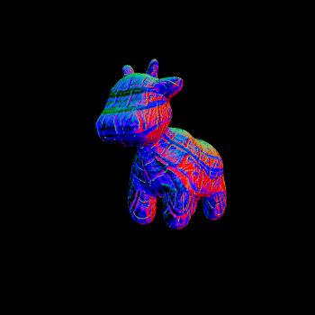
// TODO: Implement bump mapping here
// Let n = normal = (x, y, z)
// Vector t = (x*y/sqrt(x*x+z*z),sqrt(x*x+z*z),z*y/sqrt(x*x+z*z))
// Vector b = n cross product t
// Matrix TBN = [t b n]
// dU = kh * kn * (h(u+1/w,v)-h(u,v))
// dV = kh * kn * (h(u,v+1/h)-h(u,v))
// Vector ln = (-dU, -dV, 1)
// Normal n = normalize(TBN * ln)

float x = normal.x(), y = normal.y(), z = normal.z();
float u = payload.tex_coords.x(), v = payload.tex_coords.y();
int w = payload.texture->width, h = payload.texture->height;

Eigen::Vector3f t;
t << x*y / std::sqrt(x*x + z*z), std::sqrt(x*x + z*z), z*y / std::sqrt(x*x + z*z);
Eigen::Vector3f b = normal.cross(t);
Eigen::Matrix3f TBN;
TBN << t, b, normal;

auto d_u = kh * kn * (payload.texture->getColor(u+1.0f/w, v).norm() - payload.texture->getColor(u, v).norm());
auto d_v = kh * kn * (payload.texture->getColor(u/w+1.0f, v).norm() - payload.texture->getColor(u, v).norm());

Eigen::Vector3f ln(-d_u, -d_v, 1.0f);
normal = (TBN * ln).normalized();

此时运行 ./Rasterizer assignment3_bump.png bump,得到如下图片:

  1. 依然是算出新的法线,然后用这个法线影响所绘制的点的坐标
1
2
3
4
5
6
7
8
9
10
11
12
13
14
15
16
17
18
19
20
21
22
23
24
25
26
27
28
29
30
31
32
33
34
35
36
37
38
39
40
41
42
43
44
45
46
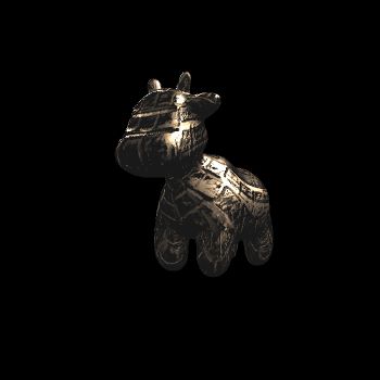
// TODO: Implement displacement mapping here
// Let n = normal = (x, y, z)
// Vector t = (x*y/sqrt(x*x+z*z),sqrt(x*x+z*z),z*y/sqrt(x*x+z*z))
// Vector b = n cross product t
// Matrix TBN = [t b n]
// dU = kh * kn * (h(u+1/w,v)-h(u,v))
// dV = kh * kn * (h(u,v+1/h)-h(u,v))
// Vector ln = (-dU, -dV, 1)
// Position p = p + kn * n * h(u,v)
// Normal n = normalize(TBN * ln)

float x = normal.x(), y = normal.y(), z = normal.z();
float u = payload.tex_coords.x(), v = payload.tex_coords.y();
int w = payload.texture->width, h = payload.texture->height;

Eigen::Vector3f t;
t << x*y / std::sqrt(x*x + z*z), std::sqrt(x*x + z*z), z*y / std::sqrt(x*x + z*z);
Eigen::Vector3f b = normal.cross(t);
Eigen::Matrix3f TBN;
TBN << t, b, normal;

auto d_u = kh * kn * (payload.texture->getColor(u+1.0f/w, v).norm() - payload.texture->getColor(u, v).norm());
auto d_v = kh * kn * (payload.texture->getColor(u/w+1.0f, v).norm() - payload.texture->getColor(u, v).norm());

Eigen::Vector3f ln(-d_u, -d_v, 1.0f);

point += kn * normal * payload.texture->getColor(u, v).norm();
normal = (TBN * ln).normalized();

Eigen::Vector3f result_color = {0, 0, 0};
Eigen::Vector3f v_ = ( -point).normalized(); // camera at (0, 0, 0)
for (auto& light : lights)
{
// TODO: For each light source in the code, calculate what the *ambient*, *diffuse*, and *specular*
// components are. Then, accumulate that result on the *result_color* object.

Eigen::Vector3f l = (light.position - point).normalized();
Eigen::Vector3f h = ((l + v_) / 2.0f).normalized();
float r2 = (light.position - point).squaredNorm();

auto L_a = ka.cwiseProduct(amb_light_intensity);
auto L_d = kd.cwiseProduct(light.intensity / r2 * MAX(0.0f, normal.dot(l)));
auto L_s = ks.cwiseProduct(light.intensity / r2 * std::pow(MAX(0.0f, normal.dot(h)), p));

result_color += L_a + L_d + L_s;
}

此时运行 ./Rasterizer assignment3_displacement.png displacement,得到如下图片:

提高部分

TODO