20年的时候,好朋友推荐了这个课程给我,简直是神仙课程!当时每天下班后就再花一个多小时来听一节课,陆陆续续听完了。最近打算重温一下这系列课程,顺便补上笔记。
图形学有一种魔力,每次学图形学相关的知识的时候,总在感叹其美妙。第一次系统地学习图形学是在大三,当时智能车已经进入了平稳的调试期,所以找了一些囤积起来的一直想学的技术书籍开始学习:Golang、图形学、Unity3D等等。
线代知识点回顾
向量
a ⃗ = ( x a , y a , z a ) T b ⃗ = ( x b , y b , z b ) T \begin{aligned}
\vec{a} &= (x_a, y_a, z_a)^T \\
\vec{b} &= (x_b, y_b, z_b)^T
\end{aligned}
a b = ( x a , y a , z a ) T = ( x b , y b , z b ) T
点乘:a ⃗ ⋅ b ⃗ = ∣ a ⃗ ∣ ∣ b ⃗ ∣ c o s θ = x a x b + y a y b + z a z b \vec{a}·\vec{b} = |\vec{a}||\vec{b}|cosθ = x_a x_b + y_a y_b + z_a z_b a ⋅ b = ∣ a ∣ ∣ b ∣ c o s θ = x a x b + y a y b + z a z b
叉乘:a ⃗ × b ⃗ = ( y a z b − y b z a , z a x b − x a z b , x a y b − y a x b ) T \vec{a}×\vec{b} = (y_a z_b - y_b z_a, z_a x_b - x_a z_b, x_a y_b - y_a x_b)^T a × b = ( y a z b − y b z a , z a x b − x a z b , x a y b − y a x b ) T ∣ a ⃗ × b ⃗ ∣ = ∣ a ⃗ ∣ ∣ b ⃗ ∣ s i n θ |\vec{a}×\vec{b}| = |\vec{a}||\vec{b}|sinθ ∣ a × b ∣ = ∣ a ∣ ∣ b ∣ s i n θ a ⃗ \vec{a} a b ⃗ \vec{b} b
点乘作用:
得到两个向量之间的夹角,特别是两个单位向量
找到一个向量对另一个向量的投影
符号表示“前”与“后”的信息
大小表示两个向量有多“接近”
叉乘作用:
判断点是否在三角形内(点P同时在三条边左边或右边)
获得坐标系
矩阵
M × N M×N M × N N × P N×P N × P 矩阵相乘A B = C AB=C A B = C C C C i i i j j j A A A i i i B B B j j j
A B = B A AB = BA A B = B A ( A B ) T = B T A T (AB)^T = B^T A^T ( A B ) T = B T A T A A − 1 = I AA^{-1} = I A A − 1 = I a ⃗ ⋅ b ⃗ = a ⃗ T b ⃗ \vec{a}·\vec{b} = \vec{a}^T\vec{b} a ⋅ b = a T b a ⃗ × b ⃗ = A ∗ b ⃗ \vec{a}×\vec{b} = A^*\vec{b} a × b = A ∗ b
变换
缩放:
( x ′ y ′ ) = ( s x 0 0 s y ) ( x y ) \begin{pmatrix}
x' \cr
y'
\end{pmatrix}
=
\begin{pmatrix}
s_x & 0 \cr
0 & s_y
\end{pmatrix}
\begin{pmatrix}
x \cr
y
\end{pmatrix}
( x ′ y ′ ) = ( s x 0 0 s y ) ( x y )
x x x s x s_x s x y y y s y s_y s y s x s_x s x s y s_y s y
切变:
( x ′ y ′ ) = ( 1 a 0 1 ) ( x y ) \begin{pmatrix}
x' \cr
y'
\end{pmatrix}
=
\begin{pmatrix}
1 & a \cr
0 & 1
\end{pmatrix}
\begin{pmatrix}
x \cr
y
\end{pmatrix}
( x ′ y ′ ) = ( 1 0 a 1 ) ( x y )
旋转(默认逆时针旋转):
( x ′ y ′ ) = ( c o s θ − s i n θ s i n θ c o s θ ) ( x y ) \begin{pmatrix}
x' \cr
y'
\end{pmatrix}
=
\begin{pmatrix}
cosθ & -sinθ \cr
sinθ & cosθ
\end{pmatrix}
\begin{pmatrix}
x \cr
y
\end{pmatrix}
( x ′ y ′ ) = ( c o s θ s i n θ − s i n θ c o s θ ) ( x y )
线性变换
x ′ = a x + b y y ′ = c x + d y \begin{aligned}
x' = ax + by \\
y' = cx + dy
\end{aligned}
x ′ = a x + b y y ′ = c x + d y
( x ′ y ′ ) = ( a b c d ) ( x y ) \begin{pmatrix}
x' \cr
y'
\end{pmatrix}
=
\begin{pmatrix}
a & b \cr
c & d
\end{pmatrix}
\begin{pmatrix}
x \cr
y
\end{pmatrix}
( x ′ y ′ ) = ( a c b d ) ( x y )
x ′ = M x x' = Mx
x ′ = M x
齐次坐标
平移变换:
( x ′ y ′ ) = ( a b c d ) ( x y ) + ( t x t y ) \begin{pmatrix}
x' \cr
y'
\end{pmatrix}
=
\begin{pmatrix}
a & b \cr
c & d
\end{pmatrix}
\begin{pmatrix}
x \cr
y
\end{pmatrix}
+
\begin{pmatrix}
t_x \cr
t_y
\end{pmatrix}
( x ′ y ′ ) = ( a c b d ) ( x y ) + ( t x t y )
与上面的x ′ = M x x' = Mx x ′ = M x
齐次坐标下:( x , y , 1 ) T (x, y, 1)^T ( x , y , 1 ) T ( x , y , 0 ) T (x, y, 0)^T ( x , y , 0 ) T
平移变换变成了:
( x ′ y ′ w ′ ) = ( 1 0 t x 0 1 t y 0 0 1 ) ⋅ ( x y 1 ) = ( x + t x y + t y 1 ) \begin{pmatrix}
x' \cr
y' \cr
w'
\end{pmatrix}
=
\begin{pmatrix}
1 & 0 & t_x \cr
0 & 1 & t_y \cr
0 & 0 & 1
\end{pmatrix}
·
\begin{pmatrix}
x \cr
y \cr
1
\end{pmatrix}
=
\begin{pmatrix}
x + t_x \cr
y + t_y \cr
1
\end{pmatrix}
⎝ ⎜ ⎛ x ′ y ′ w ′ ⎠ ⎟ ⎞ = ⎝ ⎜ ⎛ 1 0 0 0 1 0 t x t y 1 ⎠ ⎟ ⎞ ⋅ ⎝ ⎜ ⎛ x y 1 ⎠ ⎟ ⎞ = ⎝ ⎜ ⎛ x + t x y + t y 1 ⎠ ⎟ ⎞
回到了x ′ = M x x' = Mx x ′ = M x
向量的齐次坐标为0 0 0
( x ′ y ′ w ′ ) = ( 1 0 t x 0 1 t y 0 0 1 ) ⋅ ( x y 0 ) = ( x y 0 ) \begin{pmatrix}
x' \cr
y' \cr
w'
\end{pmatrix}
=
\begin{pmatrix}
1 & 0 & t_x \cr
0 & 1 & t_y \cr
0 & 0 & 1
\end{pmatrix}
·
\begin{pmatrix}
x \cr
y \cr
0
\end{pmatrix}
=
\begin{pmatrix}
x \cr
y \cr
0
\end{pmatrix}
⎝ ⎜ ⎛ x ′ y ′ w ′ ⎠ ⎟ ⎞ = ⎝ ⎜ ⎛ 1 0 0 0 1 0 t x t y 1 ⎠ ⎟ ⎞ ⋅ ⎝ ⎜ ⎛ x y 0 ⎠ ⎟ ⎞ = ⎝ ⎜ ⎛ x y 0 ⎠ ⎟ ⎞
齐次坐标下,以下有意义的运算天然成立:
而对于点+点,我们定义:
( x y w ) ⟺ ( x / w y / w 1 ) , ( w ≠ 0 ) \begin{pmatrix}
x \cr
y \cr
w
\end{pmatrix}
\iff
\begin{pmatrix}
x/w \cr
y/w \cr
1
\end{pmatrix}
, (w ≠ 0)
⎝ ⎜ ⎛ x y w ⎠ ⎟ ⎞ ⟺ ⎝ ⎜ ⎛ x / w y / w 1 ⎠ ⎟ ⎞ , ( w = 0 )
这个定义下,点+点变成了两个点的中点。
有了齐次坐标,我们所有的变换都可以写为如下的仿射变换了:
( x ′ y ′ 1 ) = ( a b t x c d t y 0 0 1 ) ⋅ ( x y 1 ) \begin{pmatrix}
x' \cr
y' \cr
1
\end{pmatrix}
=
\begin{pmatrix}
a & b & t_x \cr
c & d & t_y \cr
0 & 0 & 1
\end{pmatrix}
·
\begin{pmatrix}
x \cr
y \cr
1
\end{pmatrix}
⎝ ⎜ ⎛ x ′ y ′ 1 ⎠ ⎟ ⎞ = ⎝ ⎜ ⎛ a c 0 b d 0 t x t y 1 ⎠ ⎟ ⎞ ⋅ ⎝ ⎜ ⎛ x y 1 ⎠ ⎟ ⎞
变换组合
逆变换:x = M − 1 M x x = M^{-1}Mx x = M − 1 M x
不以原点为中心旋转:组合平移和旋转
变换的顺序很重要
先线性变换,再平移
三维变换
( x ′ y ′ z ′ 1 ) = ( a b c t x d e f t y g h i t z 0 0 0 1 ) ⋅ ( x y z 1 ) \begin{pmatrix}
x' \cr
y' \cr
z' \cr
1
\end{pmatrix}
=
\begin{pmatrix}
a & b & c & t_x \cr
d & e & f & t_y \cr
g & h & i & t_z \cr
0 & 0 & 0 & 1
\end{pmatrix}
·
\begin{pmatrix}
x \cr
y \cr
z \cr
1
\end{pmatrix}
⎝ ⎜ ⎜ ⎜ ⎛ x ′ y ′ z ′ 1 ⎠ ⎟ ⎟ ⎟ ⎞ = ⎝ ⎜ ⎜ ⎜ ⎛ a d g 0 b e h 0 c f i 0 t x t y t z 1 ⎠ ⎟ ⎟ ⎟ ⎞ ⋅ ⎝ ⎜ ⎜ ⎜ ⎛ x y z 1 ⎠ ⎟ ⎟ ⎟ ⎞
旋转:
R x ( α ) = ( 1 0 0 0 0 c o s α − s i n α 0 0 s i n α c o s α 0 0 0 0 1 ) R_x(α)
=
\begin{pmatrix}
1 & 0 & 0 & 0 \cr
0 & cosα & -sinα & 0 \cr
0 & sinα & cosα & 0 \cr
0 & 0 & 0 & 1
\end{pmatrix}
R x ( α ) = ⎝ ⎜ ⎜ ⎜ ⎛ 1 0 0 0 0 c o s α s i n α 0 0 − s i n α c o s α 0 0 0 0 1 ⎠ ⎟ ⎟ ⎟ ⎞
R y ( α ) = ( c o s α 0 s i n α 0 0 1 0 0 − s i n α 0 c o s α 0 0 0 0 1 ) R_y(α)
=
\begin{pmatrix}
cosα & 0 & sinα & 0 \cr
0 & 1 & 0 & 0 \cr
-sinα & 0 & cosα & 0 \cr
0 & 0 & 0 & 1
\end{pmatrix}
R y ( α ) = ⎝ ⎜ ⎜ ⎜ ⎛ c o s α 0 − s i n α 0 0 1 0 0 s i n α 0 c o s α 0 0 0 0 1 ⎠ ⎟ ⎟ ⎟ ⎞
R z ( α ) = ( c o s α − s i n α 0 0 s i n α c o s α 0 0 0 0 1 0 0 0 0 1 ) R_z(α)
=
\begin{pmatrix}
cosα & -sinα & 0 & 0 \cr
sinα & cosα & 0 & 0 \cr
0 & 0 & 1 & 0 \cr
0 & 0 & 0 & 1
\end{pmatrix}
R z ( α ) = ⎝ ⎜ ⎜ ⎜ ⎛ c o s α s i n α 0 0 − s i n α c o s α 0 0 0 0 1 0 0 0 0 1 ⎠ ⎟ ⎟ ⎟ ⎞
Rodrigues’ Rotation Formula:n \mathbf{n} n
R ( n , α ) = c o s ( α ) I + ( 1 − c o s ( α ) ) n n T + s i n ( α ) ( 0 − n z n y n z 0 − n x − n y n x 0 ) ⏟ N R(\mathbf{n}, α) = cos(α)\mathbf{I} + (1-cos(α))\mathbf{nn^T} + sin(α)
\underset{\mathbf{N}}{
\underbrace{
\begin{pmatrix}
0 & -n_z & n_y \cr
n_z & 0 & -n_x \cr
-n_y & n_x & 0
\end{pmatrix}
}
}
R ( n , α ) = c o s ( α ) I + ( 1 − c o s ( α ) ) n n T + s i n ( α ) N ⎝ ⎜ ⎛ 0 n z − n y − n z 0 n x n y − n x 0 ⎠ ⎟ ⎞
四元数
为了解决旋转与旋转之间的插值而引入的。
model transformation
view transformation
projection transformation
定义相机:
Position: e ⃗ \vec{e} e
Look-at / gaze direction: g ^ \hat{g} g ^
Up direction: t ^ \hat{t} t ^
实际上是将相机放在原点,朝− z -z − z y y y M v i e w = R v i e w T v i e w M_{view} = R_{view} T_{view} M v i e w = R v i e w T v i e w
T v i e w = ( 1 0 0 − x e 0 1 0 − y e 0 0 1 − z e 0 0 0 1 ) T_{view} =
\begin{pmatrix}
1 & 0 & 0 & -x_e \cr
0 & 1 & 0 & -y_e \cr
0 & 0 & 1 & -z_e \cr
0 & 0 & 0 & 1
\end{pmatrix}
T v i e w = ⎝ ⎜ ⎜ ⎜ ⎛ 1 0 0 0 0 1 0 0 0 0 1 0 − x e − y e − z e 1 ⎠ ⎟ ⎟ ⎟ ⎞
将g ^ \hat{g} g ^ − Z -Z − Z t ^ \hat{t} t ^ Y Y Y ( g ^ × t ^ ) (\hat{g}×\hat{t}) ( g ^ × t ^ ) X X X X X X ( g ^ × t ^ ) (\hat{g}×\hat{t}) ( g ^ × t ^ )
R v i e w − 1 = ( x g ^ × t ^ x t x − g 0 y g ^ × t ^ y t y − g 0 z g ^ × t ^ z t z − g 0 0 0 0 1 ) ⇒ R v i e w = ( x g ^ × t ^ y g ^ × t ^ z g ^ × t ^ 0 x t y t y t 0 x − g y − g z − g 0 0 0 0 1 ) R^{-1}_{view} =
\begin{pmatrix}
x_{\hat{g}×\hat{t}} & x_t & x_{-g} & 0 \cr
y_{\hat{g}×\hat{t}} & y_t & y_{-g} & 0 \cr
z_{\hat{g}×\hat{t}} & z_t & z_{-g} & 0 \cr
0 & 0 & 0 & 1
\end{pmatrix}
⇒
R_{view} =
\begin{pmatrix}
x_{\hat{g}×\hat{t}} & y_{\hat{g}×\hat{t}} & z_{\hat{g}×\hat{t}} & 0 \cr
x_t & y_t & y_t& 0 \cr
x_{-g} & y_{-g} & z_{-g} & 0 \cr
0 & 0 & 0 & 1
\end{pmatrix}
R v i e w − 1 = ⎝ ⎜ ⎜ ⎜ ⎛ x g ^ × t ^ y g ^ × t ^ z g ^ × t ^ 0 x t y t z t 0 x − g y − g z − g 0 0 0 0 1 ⎠ ⎟ ⎟ ⎟ ⎞ ⇒ R v i e w = ⎝ ⎜ ⎜ ⎜ ⎛ x g ^ × t ^ x t x − g 0 y g ^ × t ^ y t y − g 0 z g ^ × t ^ y t z − g 0 0 0 0 1 ⎠ ⎟ ⎟ ⎟ ⎞
(正交矩阵符合公式A − 1 = A T A^{-1}=A^T A − 1 = A T
正交投影(定义一个立方体[ l , r ] × [ b , t ] × [ f , n ] [l, r]×[b, t]×[f, n] [ l , r ] × [ b , t ] × [ f , n ] [ − 1 , 1 ] [-1, 1] [ − 1 , 1 ]
M o r t h o = ( 2 r − l 0 0 0 0 2 t − b 0 0 0 0 2 n − f 0 0 0 0 1 ) ( 1 0 0 − r + l 2 0 1 0 − t + b 2 0 0 1 − n + f 2 0 0 0 1 ) M_{ortho} =
\begin{pmatrix}
{2 \over r-l} & 0 & 0 & 0 \cr
0 & {2 \over t-b} & 0 & 0 \cr
0 & 0 & {2 \over n-f} & 0 \cr
0 & 0 & 0 & 1
\end{pmatrix}
\begin{pmatrix}
1 & 0 & 0 & -{r+l \over 2} \cr
0 & 1 & 0 & -{t+b \over 2} \cr
0 & 0 & 1 & -{n+f \over 2} \cr
0 & 0 & 0 & 1
\end{pmatrix}
M o r t h o = ⎝ ⎜ ⎜ ⎜ ⎛ r − l 2 0 0 0 0 t − b 2 0 0 0 0 n − f 2 0 0 0 0 1 ⎠ ⎟ ⎟ ⎟ ⎞ ⎝ ⎜ ⎜ ⎜ ⎛ 1 0 0 0 0 1 0 0 0 0 1 0 − 2 r + l − 2 t + b − 2 n + f 1 ⎠ ⎟ ⎟ ⎟ ⎞
透视投影(近平面比远平面小,所以把远平面挤压到跟近平面一样大就可以使用正交投影了):
M p e r s p = M o r t h o M p e r s p → o r t h o = M o r t h o ( n 0 0 0 0 n 0 0 0 0 n + f − n f 0 0 1 0 ) M_{persp} = M_{ortho}M_{persp→ortho} = M_{ortho}
\begin{pmatrix}
n & 0 & 0 & 0 \cr
0 & n & 0 & 0 \cr
0 & 0 & n+f & -nf \cr
0 & 0 & 1 & 0
\end{pmatrix}
M p e r s p = M o r t h o M p e r s p → o r t h o = M o r t h o ⎝ ⎜ ⎜ ⎜ ⎛ n 0 0 0 0 n 0 0 0 0 n + f 1 0 0 − n f 0 ⎠ ⎟ ⎟ ⎟ ⎞
使用field-of-view(fovY)和宽高比(aspect ratio)来定义一个视锥。
用来将[ − 1 , 1 ] [-1, 1] [ − 1 , 1 ]
M v i e w p o r t = ( w i d t h 2 0 0 w i d t h 2 0 h e i g h t 2 0 h e i g h t 2 0 0 1 0 0 0 0 1 ) M_{viewport} =
\begin{pmatrix}
{width \over 2} & 0 & 0 & {width \over 2} \cr
0 & {height \over 2} & 0 & {height \over 2} \cr
0 & 0 & 1 & 0 \cr
0 & 0 & 0 & 1
\end{pmatrix}
M v i e w p o r t = ⎝ ⎜ ⎜ ⎜ ⎛ 2 w i d t h 0 0 0 0 2 h e i g h t 0 0 0 0 1 0 2 w i d t h 2 h e i g h t 0 1 ⎠ ⎟ ⎟ ⎟ ⎞
光栅化
像素是一个个小方块,左下角坐标为( 0 , 0 ) (0, 0) ( 0 , 0 ) ( x + 0.5 , y + 0.5 ) (x+0.5, y+0.5) ( x + 0 . 5 , y + 0 . 5 )
通过采样获得像素点颜色
使用叉乘来判断是否像素点中心在三角形内部
只有在三角形包围盒内的像素才需要判断是否在三角形内
抗锯齿(反走样)
锯齿是 Sampling Artifacts 中的一种,Sampling Artifacts 包括:
Jaggies(锯齿)
Moire(摩尔纹)
反转的轮子(时间采样)
…
走样产生
同样的采样频率,有可能在不同频率的信号上采样出来的结果完全相同,导致我们无法区分出这个采样结果来自于哪一个信号,所以产生了走样
对图像做傅里叶变换,会看到有“十字”形状的两条亮线,这是因为做傅里叶变换时会将图像拼接很多张,而接合的部分会产生一个高频信号
时域做卷积 ⟺ \iff ⟺
采样就是在重复某个频率的内容(使用周期的δ \delta δ
反走样(Antialiasing / AA)
(核心就是降低信号频率或者提升采样频率)
增加采样率(比如硬件上增加分辨率)
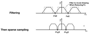
采样之前先做模糊(或者说滤波),低通滤波会将原始信号的频谱变窄,这样采样重复频谱的过程中就会让重叠部分减少,甚至不重叠
使用1像素大小的卷积核对原始图像的颜色做卷积(但实际得用一些近似方法):
MSAA (Multisample AA),假设每一个像素里面有4×4的16个小像素,使用这16个位置对图像做模糊,缺点是因为需要多用很多点来探测是否在三角形内,计算量大FXAA (Fast Approximate AA),先得到有锯齿的图,再找到图像的边界,替换这些边界为无锯齿的版本TAA (Temporal AA),不同时间使用像素的不同位置采样,把MSAA的操作分散在了时间上
深度缓存(Z-buffer)
画家算法:先画远处的物体,后画近处的物体,近处的物体会将远处的物体遮挡。需要三角形按照深度排序,但是如果三角形交叉时候无法排序。
所以引入深度缓存,对每一个像素记录其深度,而不是三角形。绘制时,遍历所有三角形,当找到某个像素点在三角形内时,先判断这个像素点在三角形上的深度,是否与Z-buffer中已有的深度相比较小,如果是则说明这个像素会遮挡已经绘制好的像素点,所以需要更新frame-buffer中对应像素点的值,以及该像素点在Z-buffer中的值。
作业0
配置环境
给定一个点 P=(2,1), 将该点绕原点先逆时针旋转 45◦,再平移 (1,2), 计算出变换后点的坐标(要求用齐次坐标进行计算)。
配置环境
使用Ubuntu-22.04来编译运行代码框架,安装C++编译环境:sudo apt-get install build-essential gdb make git
安装cmake:sudo apt-get install cmake
安装eigen库:sudo apt install libeigen3-dev
题解
添加代码:main.cpp - function main
1
2
3
4
5
6
7
8
9
10
11
12
std::cout << "\nAssignment 0: " << std::endl; Eigen::Vector3f p (2.0f , 1.0f , 1.0f ) ;Eigen::Matrix3f rotate, move; float cos45 = std::cos (45.0 /180.0 *acos (-1 ));float sin45 = std::sin (45.0 /180.0 *acos (-1 ));rotate << cos45, -sin45, 0.0 , sin45, cos45, 0.0 , 0.0 , 0.0 , 1.0 ; move << 1.0 , 0.0 , 1.0 , 0.0 , 1.0 , 2.0 , 0.0 , 0.0 , 1.0 ; std::cout << move * rotate * p << std::endl;
结果
获得输出:
1
2
3
4
Assignment 0: 1.70711 4.12132 1
作业1
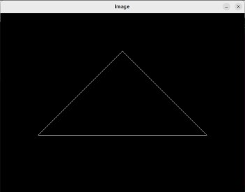
本次作业的任务是填写一个旋转矩阵和一个透视投影矩阵。给定三维下三个点 v0(2.0, 0.0, −2.0), v1(0.0, 2.0, −2.0), v2(−2.0, 0.0, −2.0), 你需要将这三个点的坐标变换为屏幕坐标并在屏幕上绘制出对应的线框三角形 (在代码框架中,我们已经提供了 draw_triangle 函数,所以你只需要去构建变换矩阵即可)。
环境配置
安装opencv:sudo apt-get install libopencv-dev python3-opencv
题解
get_model_matrix只有一个float类型的旋转角度参数,所以只需返回一个关于z z z main.cpp
1
2
3
4
5
6
7
8
9
10
11
12
13
14
15
16
17
Eigen::Matrix4f get_model_matrix (float rotation_angle) Eigen::Matrix4f model = Eigen::Matrix4f::Identity (); float cos_angle = std::cos (rotation_angle * MY_PI / 180.0 ); float sin_angle = std::sin (rotation_angle * MY_PI / 180.0 ); Eigen::Matrix4f rotation; rotation << cos_angle, -sin_angle, 0 , 0 , sin_angle, cos_angle, 0 , 0 , 0 , 0 , 1 , 0 , 0 , 0 , 0 , 1 ; return rotation * model; }
get_projection_matrix给了视角、宽高比以及远近平面的z z z
M p r o j = ( − 1 [ k t a n ( α 2 ) ] 0 0 0 0 − 1 t a n ( α 2 ) 0 0 0 0 n + f n − f 2 n f n − f 0 0 1 0 ) M_{proj} =
\begin{pmatrix}
-{1 \over [ktan({α \over 2})]} & 0 & 0 & 0 \cr
0 & -{1 \over tan({α \over 2})} & 0 & 0 \cr
0 & 0 & {n+f \over n-f} & {2nf \over n-f} \cr
0 & 0 & 1 & 0
\end{pmatrix}
M p r o j = ⎝ ⎜ ⎜ ⎜ ⎜ ⎛ − [ k t a n ( 2 α ) ] 1 0 0 0 0 − t a n ( 2 α ) 1 0 0 0 0 n − f n + f 1 0 0 n − f 2 n f 0 ⎠ ⎟ ⎟ ⎟ ⎟ ⎞
不过我这里想跟着老师的推导思路,将视锥先挤压成矩形,然后利用正交投影:main.cpp
1
2
3
4
5
6
7
8
9
10
11
12
13
14
15
16
17
18
19
20
21
22
23
24
25
26
27
28
29
30
31
32
33
34
Eigen::Matrix4f get_projection_matrix (float eye_fov, float aspect_ratio, float zNear, float zFar) Eigen::Matrix4f projection = Eigen::Matrix4f::Identity (); float angle = eye_fov * MY_PI / 180.0 ; float t = std::tan (angle / 2.0 ) * (-zNear); float b = -t; float r = t * aspect_ratio; float l = -r; Eigen::Matrix4f M_ortho_move, M_ortho_scale; M_ortho_move << 1 , 0 , 0 , -(r+l)/2.0 , 0 , 1 , 0 , -(t+b)/2.0 , 0 , 0 , 1 , -(zNear+zFar)/2.0 , 0 , 0 , 0 , 1 ; M_ortho_scale <<2.0 /(r-l), 0 , 0 , 0 , 0 , 2.0 /(t-b), 0 , 0 , 0 , 0 , 2.0 /(zNear-zFar), 0 , 0 , 0 , 0 , 1 ; Eigen::Matrix4f M_persp2ortho; M_persp2ortho <<zNear, 0 , 0 , 0 , 0 , zNear, 0 , 0 , 0 , 0 , zNear+zFar, -zNear*zFar, 0 , 0 , 1 , 0 ; return M_ortho_move * M_ortho_scale * M_persp2ortho * projection; }
结果
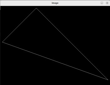
按下A或者D键会分别左右旋转一定角度。
提高部分
使用Rodrigues’ Rotation Formula:main.cpp
1
2
3
4
5
6
7
8
9
10
11
12
13
14
15
16
17
Eigen::Matrix4f get_rotation (Vector3f axis, float angle) angle = angle * MY_PI / 180.0 ; Eigen::Matrix3f N; N <<0 , -axis.z (), axis.y (), axis.z (), 0 , -axis.x (), -axis.y (), axis.x (), 0 ; Eigen::Matrix3f R = std::cos (angle) * Eigen::Matrix3f::Identity () + (1 -std::cos (angle))*axis*axis.transpose () + std::sin (angle) * N; Eigen::Matrix4f rotation = Eigen::Matrix4f::Zero (); rotation (3 , 3 ) = 1 ; rotation.block (0 , 0 , 2 , 2 ) = R.block (0 , 0 , 2 , 2 ); return rotation; }
将main函数中的r.set_model(get_model_matrix(angle));r.set_model(get_rotation(Eigen::Vector3f(-1, 1, 0), angle));( − 1 , 1 , 0 ) (-1, 1, 0) ( − 1 , 1 , 0 )
作业2
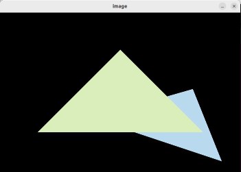
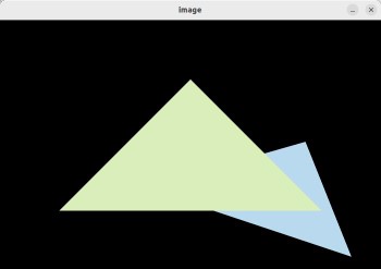
在上次作业中,虽然我们在屏幕上画出一个线框三角形,但这看起来并不是那么的有趣。所以这一次我们继续推进一步——在屏幕上画出一个实心三角形,换言之,栅格化一个三角形。
题解
对于projection矩阵,我们这次直接用推导完成的矩阵:main.cpp
1
2
3
4
5
6
7
8
9
10
11
12
13
Eigen::Matrix4f get_projection_matrix (float eye_fov, float aspect_ratio, float zNear, float zFar) Eigen::Matrix4f projection; eye_fov = eye_fov * MY_PI / 180.0 ; float ty = -1.0 / std::tan (eye_fov / 2.0 ); projection << (ty / aspect_ratio), 0 , 0 , 0 , 0 , ty, 0 , 0 , 0 , 0 , (zNear+zFar)/(zNear-zFar), (-2.0 *zNear*zFar)/(zNear-zFar), 0 , 0 , 1 , 0 ; return projection; }
对于栅格化三角形,其步骤为:
找到三角形的包围盒
遍历包围盒中的像素,判断各像素是否在三角形内部
如果是,则获得该像素在三角形中的深度值,并判断该深度值是否比现存Z-buffer中的小
若新的z值较小,则更新frame-buffer和Z-buffer
rasterizer.cpp
1 2 3 4 5 6 7 8 9 10 11 12 13 14 15 16 17 18 19 20 21 22 23 24 25 26 27 28 29 30 31 32 33 34 void rst::rasterizer::rasterize_triangle (const Triangle& t) { auto v = t.toVector4 (); float x_min = floor (std::min (std::min (v[0 ].x (), v[1 ].x ()), v[2 ].x ())); float x_max = ceil (std::max (std::max (v[0 ].x (), v[1 ].x ()), v[2 ].x ())); float y_min = floor (std::min (std::min (v[0 ].y (), v[1 ].y ()), v[2 ].y ())); float y_max = ceil (std::max (std::max (v[0 ].y (), v[1 ].y ()), v[2 ].y ())); for (int x = x_min; x < x_max; x++) { for (int y = y_min; y < y_max; y++) { if (insideTriangle (x+0.5f , y+0.5f , t.v)) { auto [alpha, beta, gamma] = computeBarycentric2D (x, y, t.v); float w_reciprocal = 1.0 /(alpha / v[0 ].w () + beta / v[1 ].w () + gamma / v[2 ].w ()); float z_interpolated = alpha * v[0 ].z () / v[0 ].w () + beta * v[1 ].z () / v[1 ].w () + gamma * v[2 ].z () / v[2 ].w (); z_interpolated *= w_reciprocal; if (z_interpolated < depth_buf[get_index (x, y)]) { Eigen::Vector3f point (x, y, 1.0f ) ; set_pixel (point, t.getColor ()); depth_buf[get_index (x, y)] = z_interpolated; } } } } }
判断一个点是否在三角形内,使用叉乘:即将各顶点与该点连成向量,将各向量与各边进行叉乘,结果的z值代表了叉乘之后的方向,如果三次叉乘都同向则说明点在三角形内。rasterizer.cpp
1
2
3
4
5
6
7
8
9
10
11
12
13
14
15
16
17
static bool insideTriangle (int x, int y, const Vector3f* _v) Eigen::Vector3f ab (_v[0 ].x() - _v[1 ].x(), _v[0 ].y() - _v[1 ].y(), 1.0f ) ; Eigen::Vector3f bc (_v[1 ].x() - _v[2 ].x(), _v[1 ].y() - _v[2 ].y(), 1.0f ) ; Eigen::Vector3f ca (_v[2 ].x() - _v[0 ].x(), _v[2 ].y() - _v[0 ].y(), 1.0f ) ; Eigen::Vector3f ap (_v[0 ].x() - x, _v[0 ].y() - y, 1.0f ) ; Eigen::Vector3f bp (_v[1 ].x() - x, _v[1 ].y() - y, 1.0f ) ; Eigen::Vector3f cp (_v[2 ].x() - x, _v[2 ].y() - y, 1.0f ) ; float z1 = ab.cross (ap).z (); float z2 = bc.cross (bp).z (); float z3 = ca.cross (cp).z (); return (z1 > 0 && z2 > 0 && z3 > 0 ) || (z1 < 0 && z2 < 0 && z3 < 0 ); }
结果
提高部分
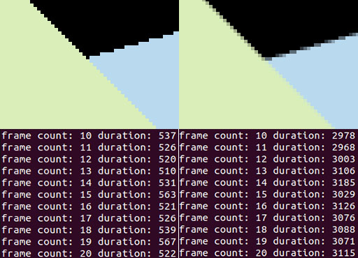
提高部分要求用SSAA,而课堂上讲的是MSAA。区别在于:
MSAA (Multisample AA) 是利用每个像素点中多个点进行采样,达到“模糊”的目的,之后再将像素点中心的颜色显示出来。
SSAA (Supersampling AA) 相当于渲染了一张更高分辨率的图片,然后将一个像素覆盖的几个子像素做平均,再显示。
增加SSAA所需要维护的子像素缓冲,顺便加一个开关方便后续对比:rasterizer.hpp - class rasterizer
1
2
3
4
5
6
7
8
9
10
11
12
class rasterizer { public : rasterizer (int w, int h, bool use_2xSSAA = false ); private : bool enable_2xSSAA; std::vector<Eigen::Vector3f> frame_buf; std::vector<std::vector<Eigen::Vector3f>> frame_buf_2xSSAA; std::vector<float > depth_buf; std::vector<std::vector<float >> depth_buf_2xSSAA; };
增加对每个子像素都进行处理的代码:rasterizer.cpp - function rst::rasterizer::rasterize_triangle
1 2 3 4 5 6 7 8 9 10 11 12 13 14 15 16 17 18 19 20 21 22 23 24 25 26 27 28 29 30 31 32 33 34 35 std::vector<float > coord_offset{0.25 , 0.75 }; for (int x = x_min; x < x_max; x++) { for (int y = y_min; y < y_max; y++) { if (enable_2xSSAA) { int idx = 0 ; for (auto i : coord_offset) { for (auto j : coord_offset) { if (insideTriangle (x+i, y+j, t.v)) { auto [alpha, beta, gamma] = computeBarycentric2D (x+i, y+j, t.v); float w_reciprocal = 1.0 /(alpha / v[0 ].w () + beta / v[1 ].w () + gamma / v[2 ].w ()); float z_interpolated = alpha * v[0 ].z () / v[0 ].w () + beta * v[1 ].z () / v[1 ].w () + gamma * v[2 ].z () / v[2 ].w (); z_interpolated *= w_reciprocal; if (z_interpolated < depth_buf_2xSSAA[get_index (x, y)][idx]) { frame_buf_2xSSAA[get_index (x, y)][idx] = t.getColor (); depth_buf_2xSSAA[get_index (x, y)][idx] = z_interpolated; } } idx++; } } } else { if (insideTriangle (x+0.5f , y+0.5f , t.v)) { auto [alpha, beta, gamma] = computeBarycentric2D (x, y, t.v); float w_reciprocal = 1.0 /(alpha / v[0 ].w () + beta / v[1 ].w () + gamma / v[2 ].w ()); float z_interpolated = alpha * v[0 ].z () / v[0 ].w () + beta * v[1 ].z () / v[1 ].w () + gamma * v[2 ].z () / v[2 ].w (); z_interpolated *= w_reciprocal; if (z_interpolated < depth_buf[get_index (x, y)]) { Eigen::Vector3f point (x, y, 1.0f ) ; set_pixel (point, t.getColor ()); depth_buf[get_index (x, y)] = z_interpolated; } } } } }
新增加的两个缓存也需要做初始化以及初值填充:rasterizer.cpp
1
2
3
4
5
6
7
8
9
10
11
12
13
14
15
16
17
18
19
20
21
22
23
24
25
26
27
28
29
30
31
32
33
void rst::rasterizer::clear (rst::Buffers buff){ if ((buff & rst::Buffers::Color) == rst::Buffers::Color) { std::fill (frame_buf.begin (), frame_buf.end (), Eigen::Vector3f{0 , 0 , 0 }); if (enable_2xSSAA) { for (int i = 0 ; i < frame_buf_2xSSAA.size (); i++) { frame_buf_2xSSAA[i].resize (4 ); std::fill (frame_buf_2xSSAA[i].begin (), frame_buf_2xSSAA[i].end (), Eigen::Vector3f{0 , 0 , 0 }); } } } if ((buff & rst::Buffers::Depth) == rst::Buffers::Depth) { std::fill (depth_buf.begin (), depth_buf.end (), std::numeric_limits<float >::infinity ()); if (enable_2xSSAA) { for (int i = 0 ; i < depth_buf_2xSSAA.size (); i++) { depth_buf_2xSSAA[i].resize (4 ); std::fill (depth_buf_2xSSAA[i].begin (), depth_buf_2xSSAA[i].end (), std::numeric_limits<float >::infinity ()); } } } } rst::rasterizer::rasterizer (int w, int h, bool use_2xSSAA) : width (w), height (h), enable_2xSSAA (use_2xSSAA) { frame_buf.resize (w * h); depth_buf.resize (w * h); if (enable_2xSSAA) { frame_buf_2xSSAA.resize (w * h); depth_buf_2xSSAA.resize (w * h); } }
实际显示时,需要对子像素做平均:rasterizer.cpp - function rst::rasterizer::draw
1
2
3
4
5
6
7
8
9
10
11
12
13
rasterize_triangle (t);if (enable_2xSSAA) { for (int x = 0 ; x < width; x++) { for (int y = 0 ; y < height; y++) { Eigen::Vector3f color (0 , 0 , 0 ) ; for (int i = 0 ; i < 4 ; i++) { color += frame_buf_2xSSAA[get_index (x, y)][i]; } color /= 4 ; set_pixel (Eigen::Vector3f (x, y, 1.0f ), color); } } }
最后修改main函数中的逻辑:main.cpp - function main
1
2
3
4
5
6
7
8
9
10
11
rst::rasterizer r (700 , 700 , false ) ;while (key != 27 ){ long long frame_begin_time = get_timestamp (); long long frame_time = get_timestamp () - frame_begin_time; std::cout << "frame count: " << frame_count++ << " duration: " << frame_time << '\n' ; }
添加时间戳函数:main.cpp
1 2 3 4 5 6 7 8 9 10 11 12 13 14 15 #include <sys/time.h> #include <time.h> long long get_timestamp (void ) long long tmp; struct timeval tv; gettimeofday (&tv, NULL ); tmp = tv.tv_sec; tmp = tmp * 1000 ; tmp = tmp + (tv.tv_usec / 1000 ); return tmp; }
结果:
将抗锯齿开启与不开启的图像做对比,效果还是非常显著的(效率下降也是非常显著的):
